Projects
In this page I have included two of the projects I have recently been working on. One of the projects I have contributed to through Georgia Tech’s Robo Jacket team is an autonomous rover machine that navigates and explores with no external control system. The other small project was for the ECE 1100 introductory class at Georgia Institute of Technology. You can learn more about these projects by navigating down this page.
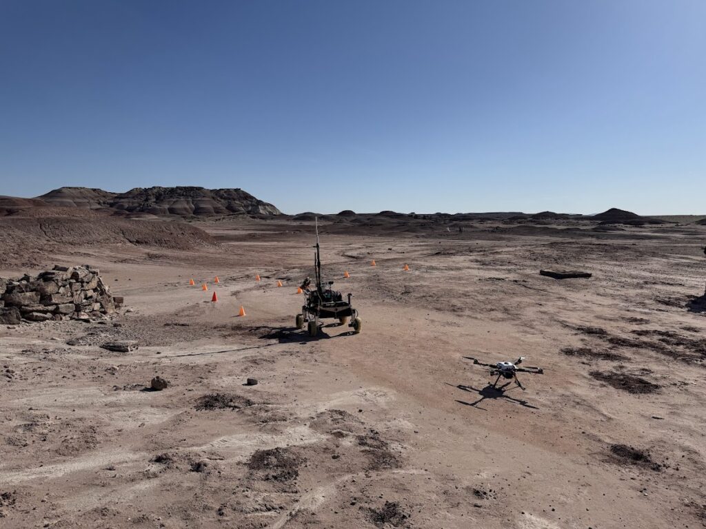
RoboJackets RoboNAV – Mars Rover Project
Overview:
RoboNav is one of the core projects of the RoboJackets team at Georgia Tech. It is focused on building an autonomously navigating rover for exploring Mars-like environments. RoboNAV has four teams each working on different parts of the rover. I am currently in the software team, which is responsible for the “brains” of the rover. I am a new member in the RoboNAV team, so I have been in the training phase learning about the systems and softwares, as well as the theoretical parts used for this project.
Through this experience, I am gaining exposure to:
– Robotics system architecture
– Sensor integration and data processing
– Autonomous navigation concepts
– Team-based engineering workflows
My role:
Currently, I am focused on getting the foundational knowledge and preparing to contribute to the development of the rover. Training mainly includes understanding the hardware and software and completing required training modules.
Technologies and Software:
Technologies: C++, Python, ROS (Robot Operating System), embedded systems, sensors

ECE 1100 Project - Reaction Timer
Overview:
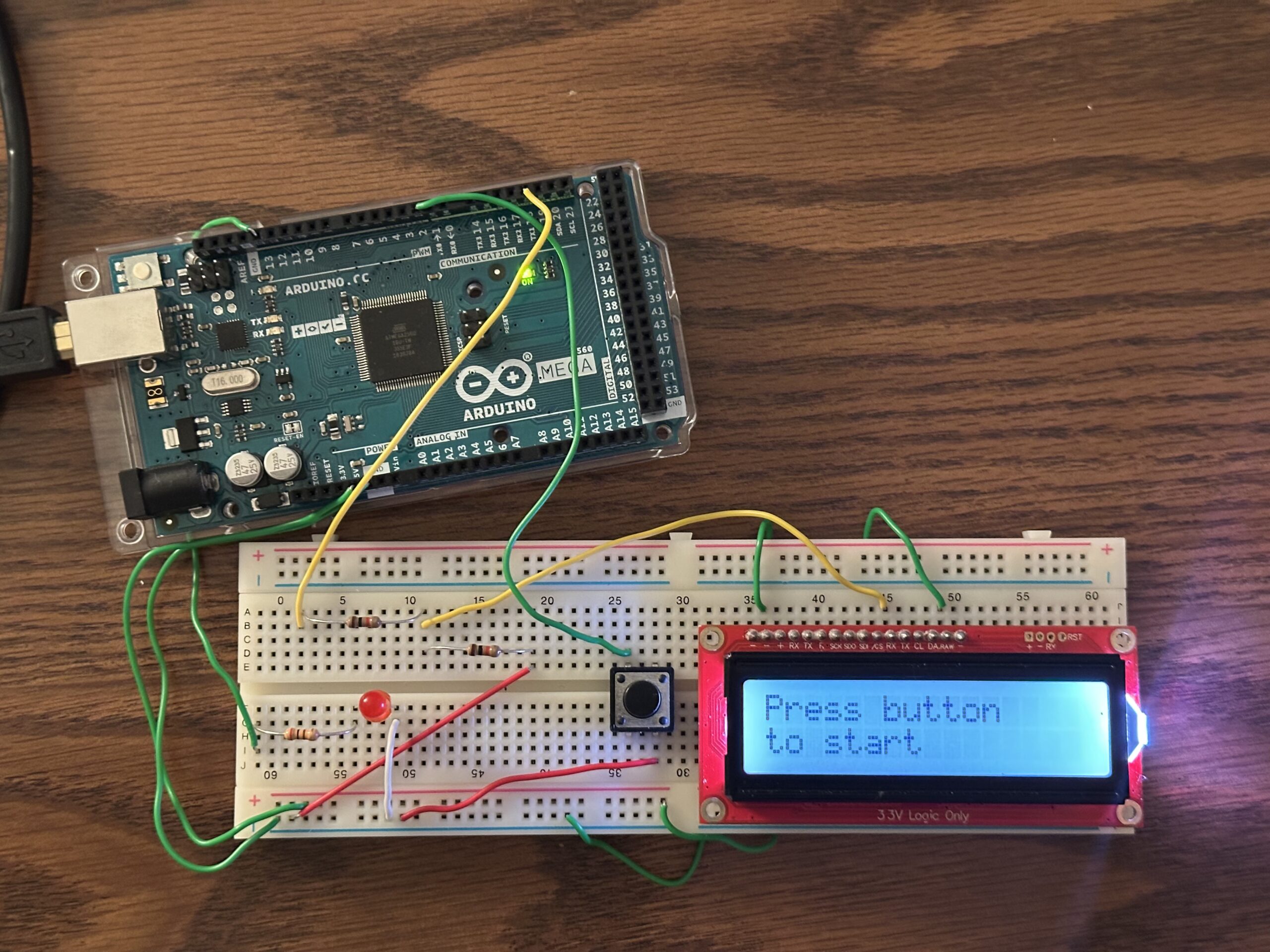
Completion of this project is part of the ECE 1100 course curriculum. Students are able to freely choose what they make for the project, as the main purpose is to explore and try getting exposure to something new. Having limited time, I have decided to make a reaction time button with an LCD screen that outputs your reaction time and instructions on how to use it. The reason I chose this project is to get exposure to using a microcontroller as well as an LCD screen.
Process:
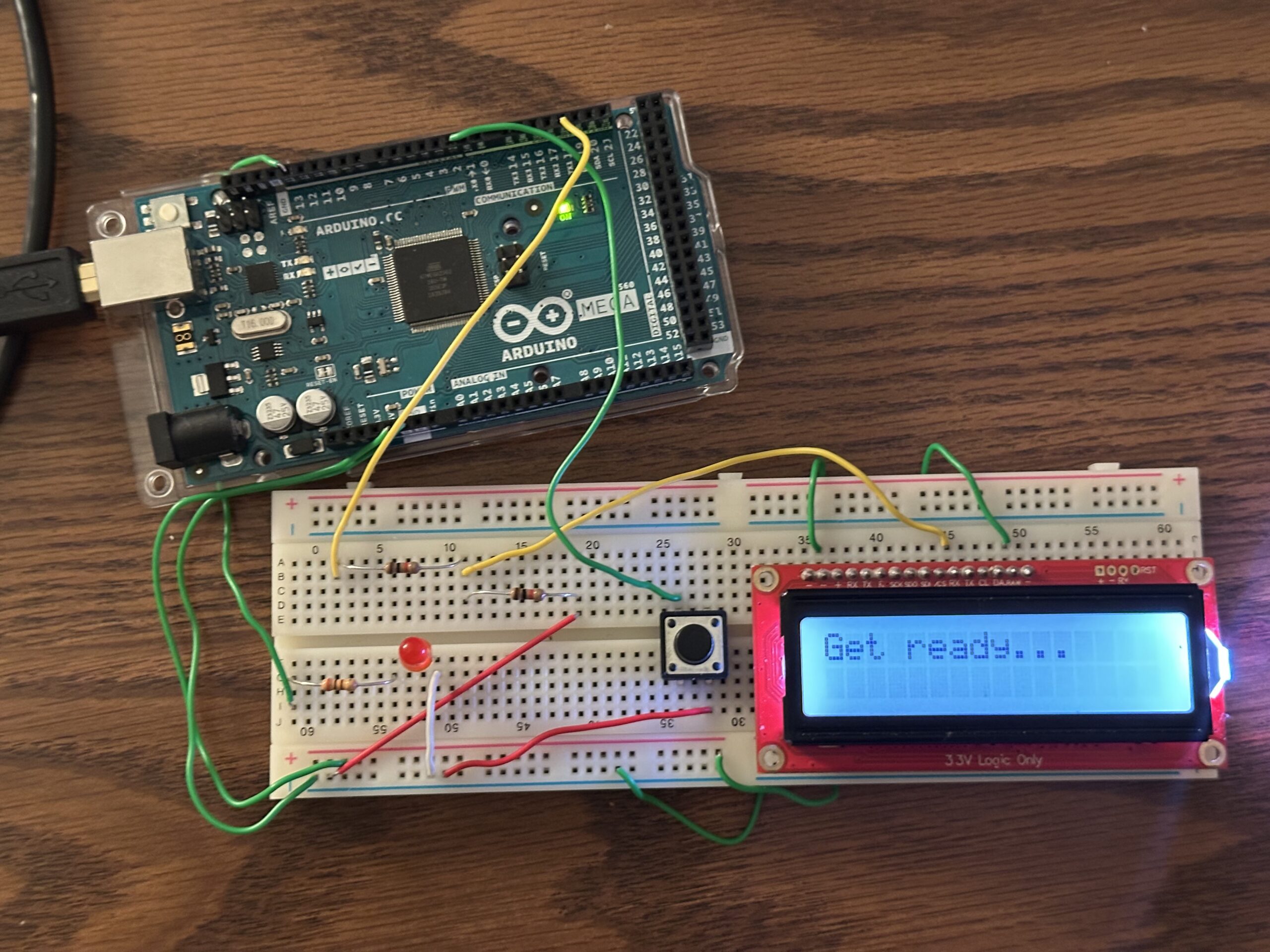
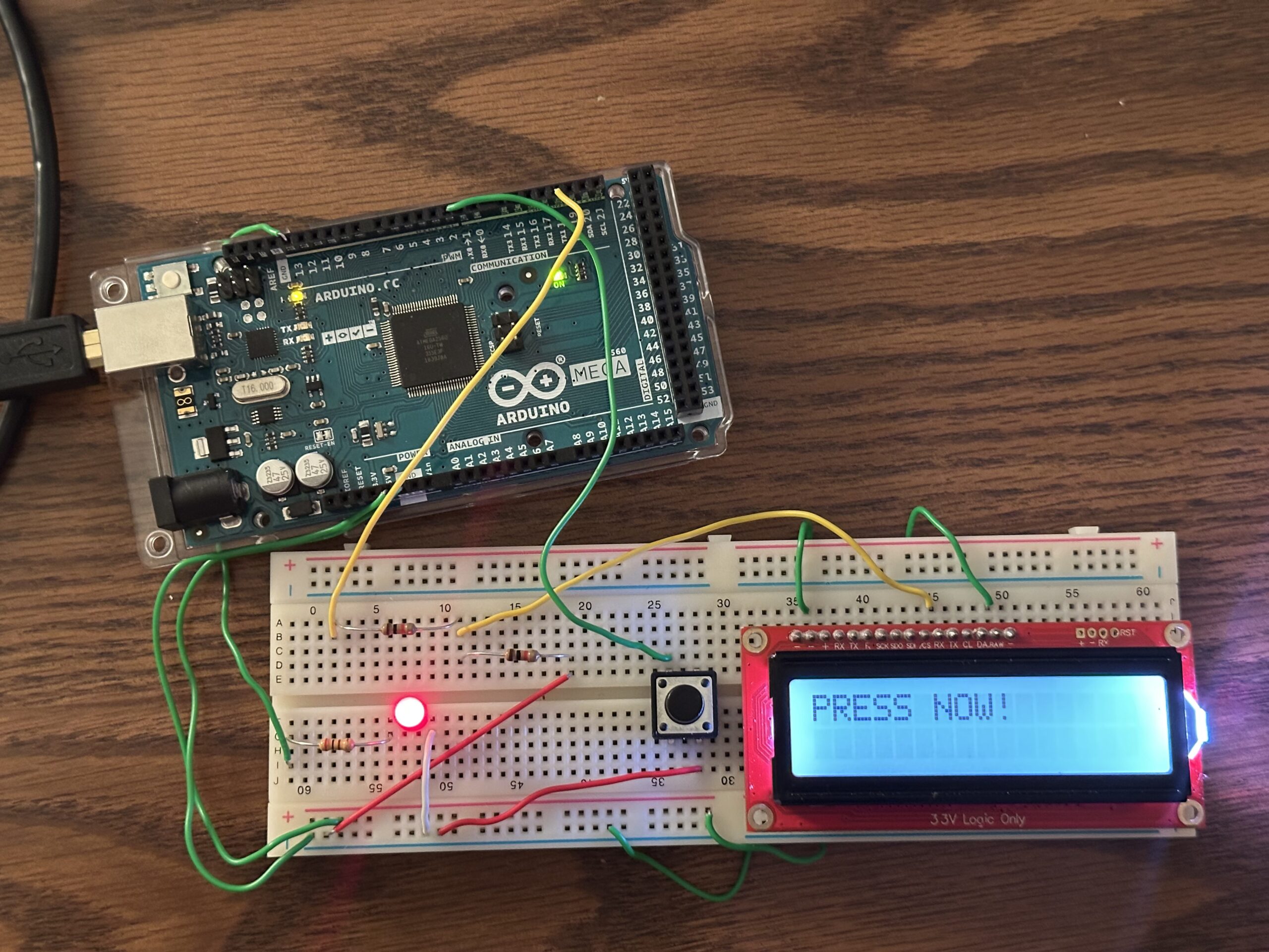
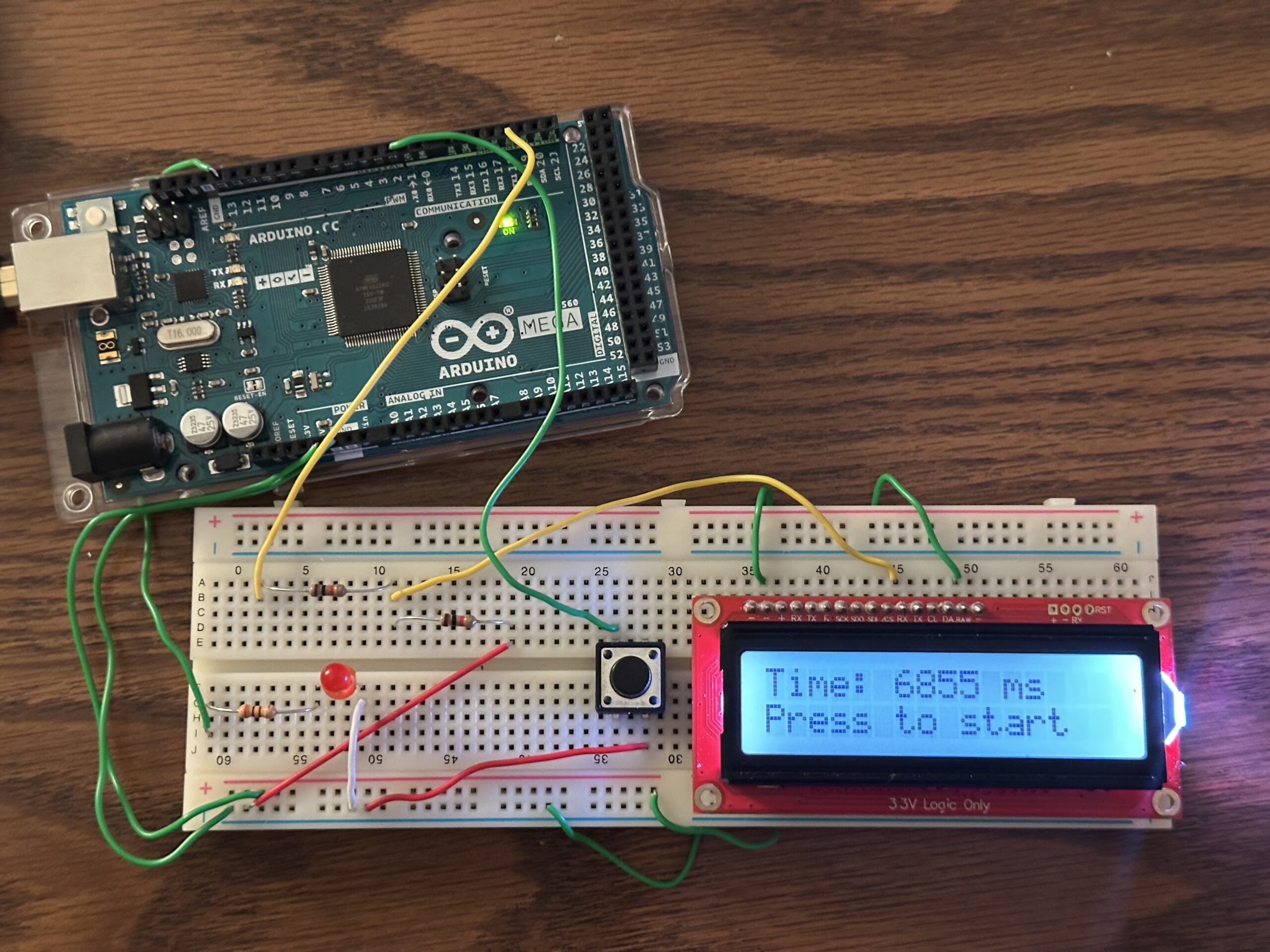
To assemble the hardware I used an LED, resistors, a push button, an LCD, and an Arduino Mega. Having assembled the hardware, I have programmed the pins of the microcontroller as needed, using the Arduino IDE. The way the reaction timer works is as follows. First, the LCD tells you to push the button to start. Having pushed the button, you wait for the LED to light up. As soon as the LED lights up, you press the button again to measure your reaction time, which will appear on the LCD. To have another try you press the button as said on the LCD.
Skills Gained:
In this project, I have used an LCD and a microcontroller for the first time. Having completed this project, I gained experience and understanding on how to use these parts. Now I have a better idea on how an Arduino microcontroller works, which encourages me to try making a more complex project using it.